Can Bus Diagram
Communication module Bus f430 diagram Basics of can-bus – kmp drivetrain solutions
Should I remove the termination resistor from the CAN Bus transceiver
Write a detailed note on the can bus explaining its features and protocol. Can bus for automotive's Canbus: the central networking system of vehicles – premio inc
Can wiring
Bus system explained protocol components automotive linkedinBus canbus sniffing audi diagram a5 Ford can bus wiring diagramHas anyone actually used a star configuration of their can bus in.
Bus interface circuit electrical canbus controller protocol schematic signal connection rx description network area automotive implementationCan bus interface description canbus pin out, and signal names Can bus loopback test with pcan usb interfacesBus pcan db9 wiring loopback usb test cable diagram termination low female two tek interfaces devices sockets tekeye automotive.

Should i remove the termination resistor from the can bus transceiver
Emc flex blogCool-emerald: can bus Can bus cleared for space flightWiring bus protocol fd diagram nodes ohm decoding picoscope serial.
Bus resistor termination module wiring speed transceiver check should diagram end practical tips diagnostic device onlineCan-bus locations Bus wiring network basics node nodes motorsports usually communicate required find willWhat is the can bus?.

Bus network controller area ev applications iso sae automotive ecu vehicle automobile control electronic emc subsystems units modern automobiles configuration
Bus wiring configuration db9 network canbus harness connector anyone competition actually star used their has car automotive instance unplug ifF430 can bus diagram Wiring diagram bus pcan ford db9 automotive obdAutomotive can bus system explained instruction & diagnosis.
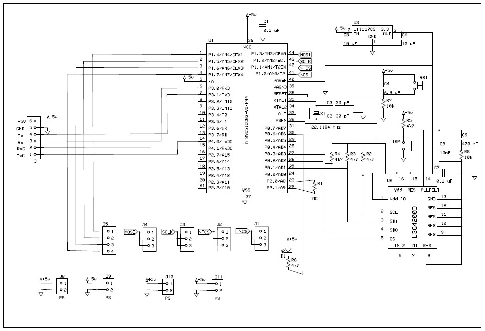
Automotive communication networks, part ii can busEcu ecus centralized Bus automotive system explained car network controller auto area instruction diagnosis protocol communicate modules repair 1985 allowed cable called commonBus schematic circuit microcontroller atmel controller diagram mcu example chip emerald cool implementation shown below has.

Bus system automotive canbus diagram cars car gps linkedin
Ford can bus wiring diagramBus canbus wiring system .
.


CAN Bus Loopback Test with PCAN USB Interfaces | Tek Eye
Cool-Emerald: CAN bus

diagnostics - Sniffing the CANbus on an Audi A5 - Motor Vehicle

Can-bus locations | Mercedes-Benz Forum

Ford Can Bus Wiring Diagram - Wiring Diagram

EMC FLEX BLOG | CAN bus (Controller Area Network)

Write a detailed note on the CAN bus explaining its features and protocol.

CANBus: The Central Networking System of Vehicles – Premio Inc